How stable are construction profiles?
Posted on Feb 25, 2025
Step by step explains how to calculate the deflection of structural profiles under load .
Construction profiles are highly resilient. However, this does not mean that they do not bend under load. We explain step by step how to calculate how much a profile bends using a practical example.
Calculate the load capacity of construction profiles – this is how it's done
The load-bearing capacity of construction profiles is basically quite easy to calculate. To do this, you need to know that the load capacity essentially depends on how much load may act on a profile or a construction without the profile bending too much or, in the worst case, even becoming permanently deformed.
How much a construction profile bends depends on several factors. In addition to constant values, the physical material properties, but also the weight and length of the profile, as well as the load that it will later carry, must be taken into account.
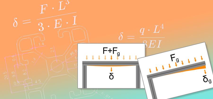
The formula for deflection is based on the classical bending theory for a beam or, as in our case, a profile that is loaded with a uniformly distributed load. The deflection of a profile is proportional to the load, the length of the profile and the modulus of elasticity of the material, and inversely proportional to the moment of inertia of the cross-section. In simple terms, this means that an identical profile with increasing length deflects more.
The way the profile is mounted also affects the load capacity, as does the load distribution. If the weight is distributed evenly over the entire length of the profile, it will bend less than if the same weight is applied to the centre of the length. A profile placed on both sides will bend more than a profile that is firmly mounted on both sides under the same load. If it is mounted on one side, the deflection factor is even higher. Constant values are used for this, which are included in the calculation.
It all sounds very complicated, but we will approach the calculation of the deflection step by step and examine all the factors involved in detail.
Calculation of the load effects on and through the profile
Before we can calculate the deflection of the profiles, we need information about the load. It should be noted that the force of the load is given in newtons (N). Weight, on the other hand, is a mass, which in turn is measured in kilograms (kg). The relationship between force and mass is determined by the law of gravity. This means that we have to convert the mass (kilograms) into the force (Newtons). This is because one Newton does not correspond to one kilogram, so we have to include the gravitational constant here. To put it simply, this is the force of gravity, because it can be assumed that the structures are to be built on Earth and not on the Moon or Mars, where the value of the gravitational constant is significantly lower.
A distinction is made between the deflection caused by the force of the profile's own weight and the deflection caused by the force of an additional weight that also acts on the profile. To do this, the two forces acting must be determined.
Parameters for calculating the weight Fg
- m mass (weight per metre) of the profile in kg/m
- Construction profile 20x20, groove 6: Weight: 0,461 kg/m
- Construction profile 30x30, groove 8: Weight: 0,742 kg/m
- Construction profile 40x40, groove 8: Weight: 1,207 kg/m
- l The length of the profile in metres
- g The gravitational constant (approx. 9.81m/s 2)
To determine the weight of the profile, the profile length must be multiplied by the weight per metre. Alternatively, you can simply weigh the profile in the desired length. The result is multiplied again by the gravitational constant. This concludes the calculation.
The formula for calculating the weight
For a 2-metre long construction profile 40x40mm groove 8 with a mass of 1.207kg per metre, the formula is as follows
Parameters for converting the weight loadF
- mThe mass or weight in kg with which the profile will be loaded later
- gThe gravitational constant (approx. 9.81m/s 2)
The force acting on the profile in addition to its own weight is determined by simply multiplying the weight by the gravitational constant. If the construction, or the specific profile, is not additionally loaded, the value is not required to calculate the total deflection.
The formula for calculating the weight load
With an expected maximum weight of 100kg acting on the individual profile, the following calculation results.
Calculation of the deflection of a structural profile
Now that we know the force of the load application, we can turn to the really important calculation: the bending of a profile. As mentioned in the introduction, we need additional values for this. Without which a calculation would not be possible. The modulus of elasticity of the aluminium used in an EN AW 6063 T5 alloy is 69GPa (69,000MPa), which converts to 69,000N/mm². This physical value is dependent on the material and is therefore identical for all three profile sizes that we offer. We already know the profile length, otherwise we would not have been able to calculate the weight of the empty weight. Since the moment of inertia, as a measure of the bending properties of the cross-section, depends on the specific profile, we have to determine this value in the technical specifications for this profile.
These formulas also use fixed factors. These relate to the geometry of the bend and are the result of calculations that take into account the profile in its specific load form. It may not sound very clear at first. With a point load, the entire weight acts on a small area, for example in the middle of the beam. If, on the other hand, this is distributed over the entire length, the deflection is less. If the profile is mounted on one or both sides, these parameters change again. With constant numerical values, which are used in the formula at specified points, we achieve a correct calculation. This means that we first need to know how the profile is mounted. We also need to be clear about the type of load, but be careful – when it comes to dead weight, the load distribution is always even. This is logical, after all, the weight is distributed evenly over the entire length of a construction profile.
Constants for the formulas for deflection according to load distribution and type of mounting
- Beidseitig fest montiert:
- Deflection with even load distribution
n(F) 5 (5 times the value of the force of the total weight F + Fg)
n(E) 384 (384 times the value of the modulus of elasticity E)
Ln 4 (The fourth power of the profile length L) - Deflection due to weight loading with a centred load
n(F) 1 (1 times the value of the force of the weight load F)
n(E) 48 (48 times the value of the modulus of elasticity E)
Ln 3 (the cube of the profile length L)
- Deflection with even load distribution
- Permanently mounted on one side:
- Deflection with even load distribution
n(F) 1 (1 times the value of the force of the total weight force F + Fg)
n(E) 8 (8 times the value of the modulus of elasticity E)
Ln 4 (The fourth power of the profile length L) - Deflection due to weight load at the end of the open profile
n(F) 1 (1 times the value of the force of the total weight force F + Fg)
n(E) 3 (triple the value of the modulus of elasticity E)
Ln 3 (the cube of the profile length L)
- Deflection with even load distribution
Parameters for calculating the deflection under its own weightδg
- Fg The weight of the profile in newtons
- l The length of the profile in millimetres
- E The modulus of elasticity of the material in N/mm²
- n(F) Factor for the force value due to weight Fg (see above)
- n(E) factor for the modulus of elasticity E (see above)
- I The moment of inertia of the component in cm 4
- Construction profile 20x20, groove 6: moment of inertia Ix, Iy: 0,71cm4
- Construction profile 30x30, groove 8:moment of inertia Ix, Iy: 2,35cm4
- Construction profile 40x40, groove 8: moment of inertia Ix, Iy: 7,17cm4
The deflection δg is the maximum deformation of the profile due to its own weight. It depends heavily on the profile length and the geometry of the cross-section. A longer profile will bend more. With the same length, a thinner profile with a lower moment of inertia I ill also bend more under the same natural elasticity. If we stick with the example from above and assume a double-sided fixed mounting, the following formula results with the factors 5 for the weight and 384 for the modulus of elasticity. Since the dead weight does not act on one point but is distributed over the entire length, we have to calculate the surface load q, to see how many newtons of load act on one millimetre. This is quite simple and could easily be integrated into the large formula, but for a better understanding, we will separate it.
The formula for calculating the surface load
For a 2-metre long construction profile 40x40mm groove 8 with a weight of Fg 23.68N, the formula is as follows.
Now we know all the parameters for determining how much the profile bends. We can now enter the constants and calculated values in the following formula. But be careful – for the length, the fourth power must be determined for an even load distribution. Explanation: in the fourth power, the number is multiplied by itself. The result is then multiplied again by the given number and then one more time. 2000 * 2000 * 2000 * 2000 = 16,000,000,000,000 or 1.6e+13.
The deflection δg is the maximum deflection of the profile due to its own weight.
Without additional weight, i.e. based on its own weight alone, the 40mm construction profile will bend by a maximum of half a millimetre. However, in a bed frame, the profile is additionally loaded by the weight of the mattress, the bedding and the body weight. Let's assume a total weight of 100kg. This is roughly distributed lengthwise, so it can be assumed that the distribution is even. The procedure is identical.
The formula for calculating the total surface load
Calculation of the deflection due to the distributed load
A deflection of 2.1 cm may sound like a lot at first, but it actually has no effect on the deformation. In addition, the load will by no means only act on this one profile, but will be distributed around the bed frame. Nevertheless, it is possible to mount an additional support in the middle to counteract the deflection. In this case, the deflection of the respective 1000mm lengths between the mounting and support points would be considerably lower at around 1.2mm.
Parameters for calculating the deflection of the weight load δF
- FThe force applied by the weight in newtons
- lThe length of the profile in millimetres
- E The modulus of elasticity of the material in N/mm ²
- n(F) Factor for the value of the force due to weight loading F (see above)
- n(E) factor for the modulus of elasticity E (see above)
- I The moment of inertia of the component in mm 4 (siehe oben)
The formula for deflection under central point load when mounted on both sides
Let's use the same parameters, i.e. 100kg, or 981N for a 2-metre 40x40 construction profile, groove 8.
Parameters for calculating the deflection of the total load δ
- δg The deflection of the profile under the load of its own weight
- δF The deflection of the profile under the additional weight load
A 2000mm long 40x40 construction profile will therefore bend a maximum of 34mm when mounted on both sides if an additional weight of 100kg is applied to it in the middle. We are now finished with that. Whether the deflection has an effect on the dimensional stability and whether it deforms permanently is a completely different calculation, which we will explain in another blog article. At this point, however, we can already reveal that with a double-sided fastening and a point load of less than 140kg, our 2-metre-long 40-mm profile will not be permanently deformed. With an even load distribution, there is even a load limit of around 285kg.
We hope that the explanations of the calculation of the deflection of our construction profiles are helpful and understandable. The formulas are generally valid, although the constant material parameters have to be changed. In this way, the deflection of a wooden beam, an MDF board or a plasterboard can also be calculated, which can be particularly useful when renovating old buildings on your own. The necessary information can usually be found in the manufacturer's data sheets.
If you want to stay up to date, want to know what moves us and what is going on in our online shop, follow us on Instagram und Facebook. We appreciate every like.
Your Sascha from S-Polytec